Bad mirror
A smart mirror, except extremely dumb, made with a Raspberry Pi and WS281x LEDs
"Bad mirror" on https://aligot-death.space, available at https://aligot-death.space/projects/bad-mirror-en
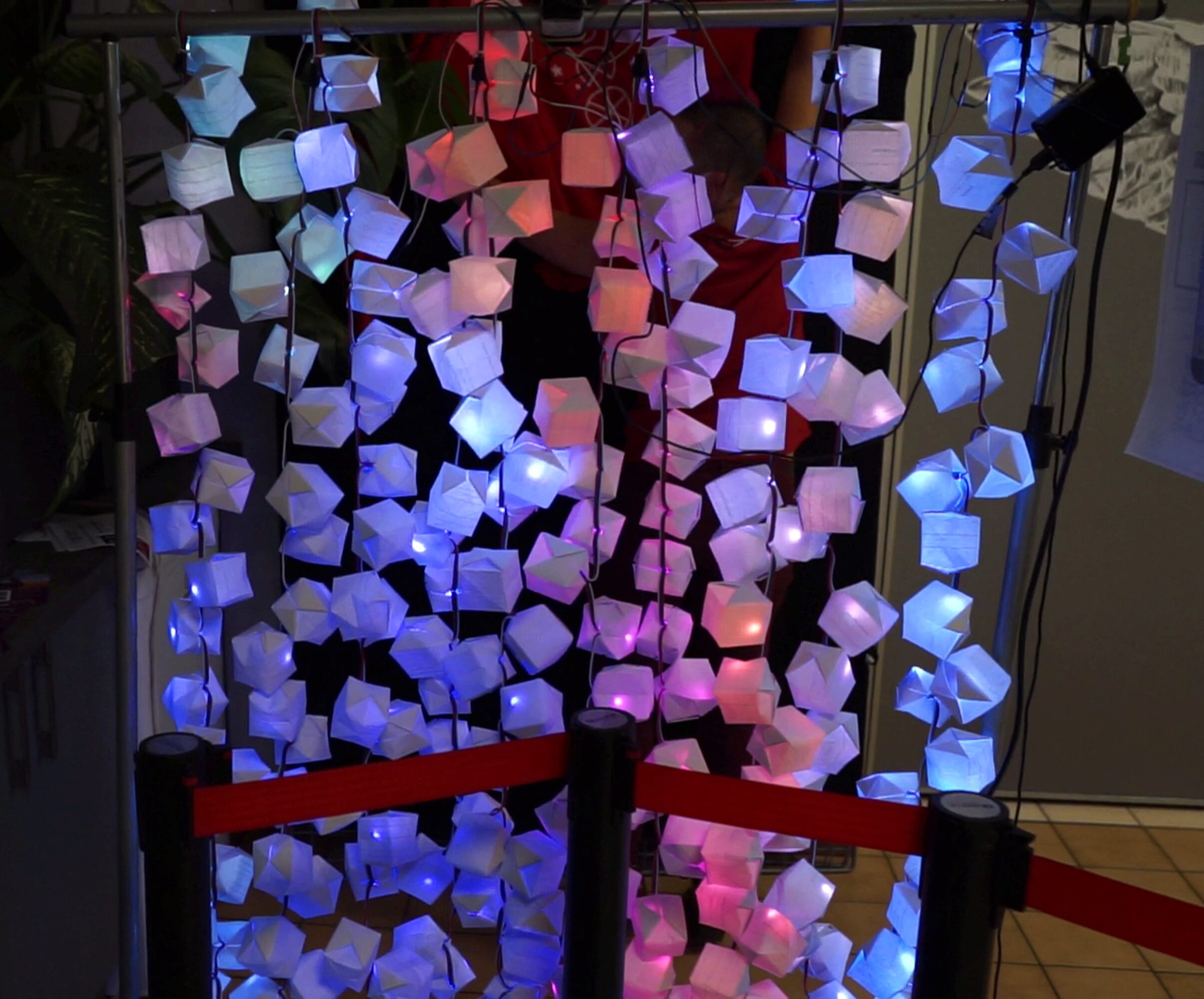
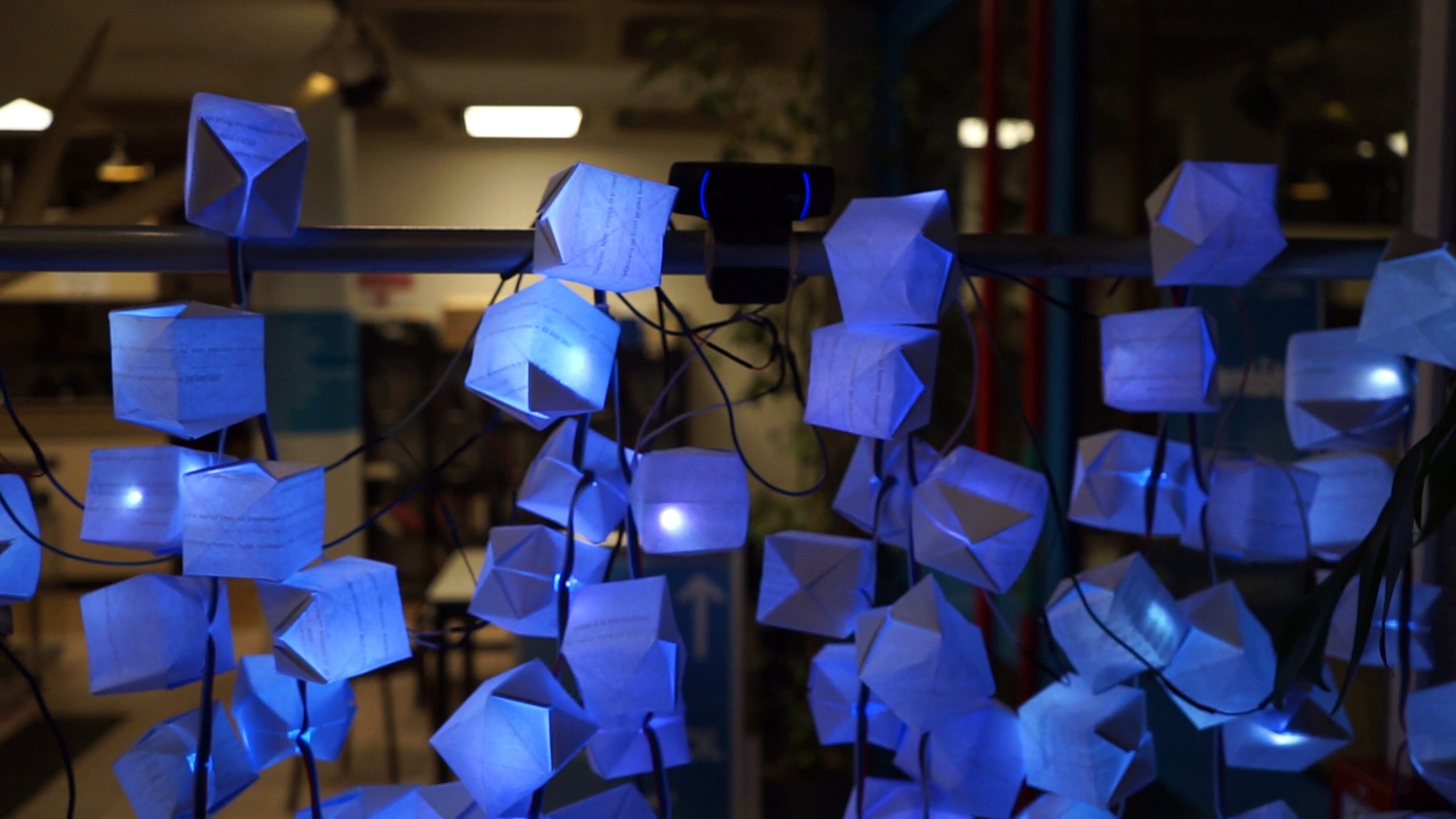
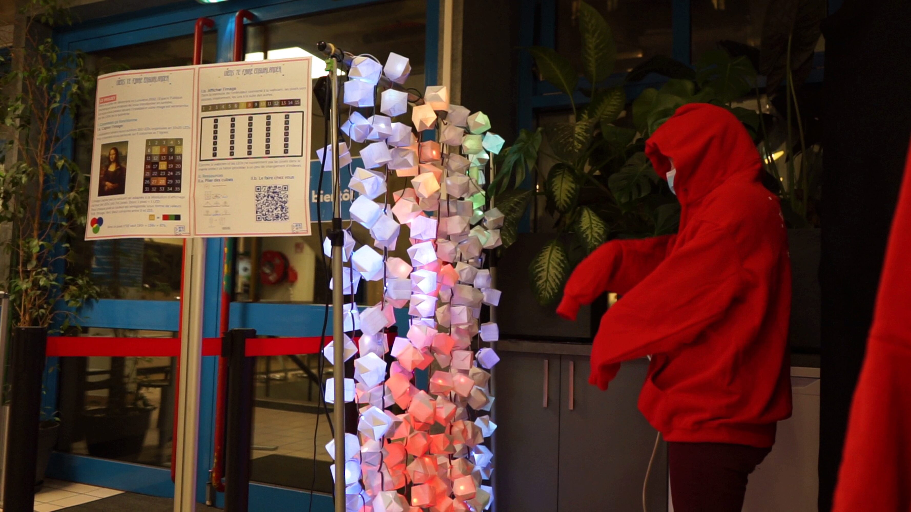
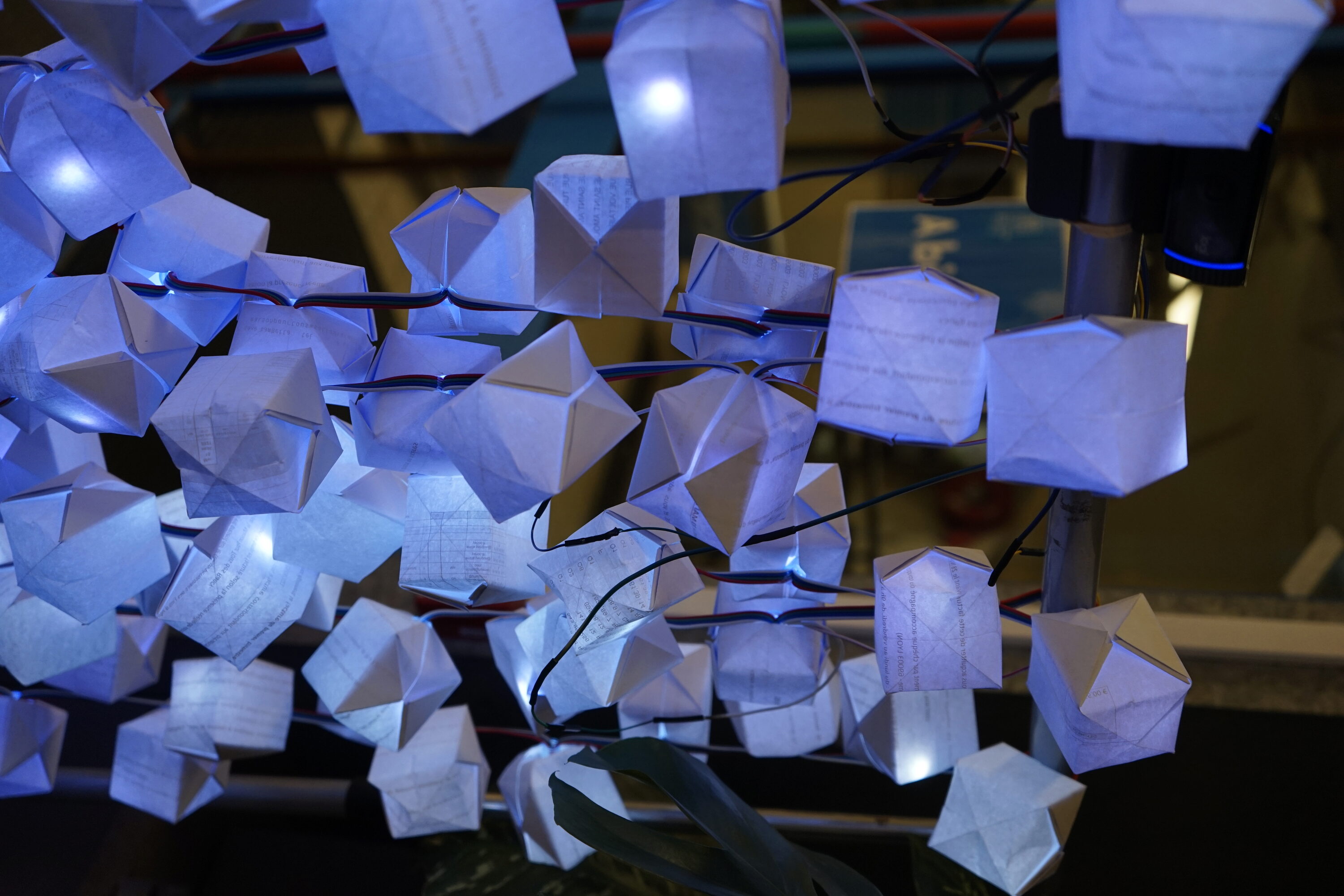
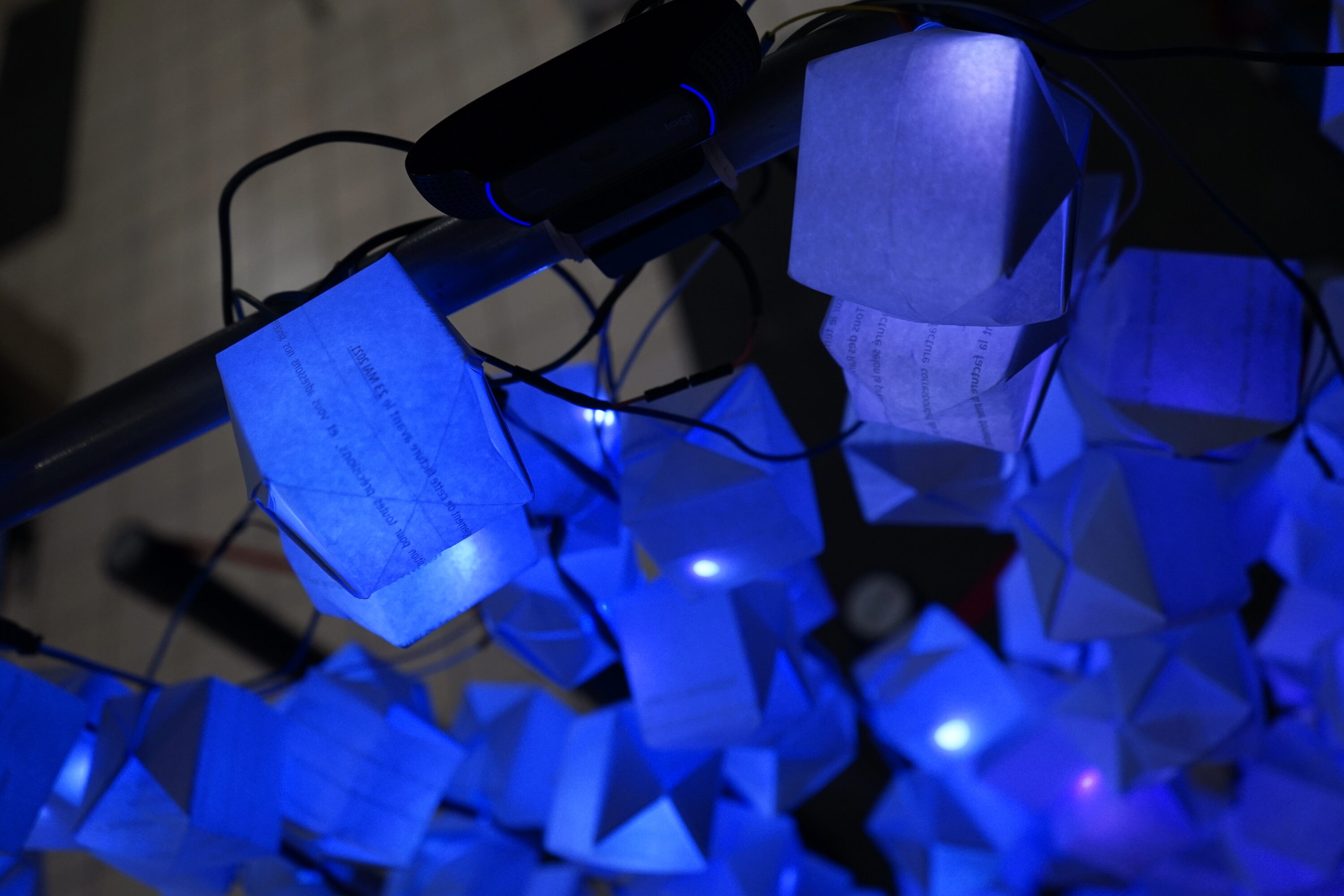
This project uses a Raspberry Pi to turn a LED strip covered with paper boxes into a mirror using a webcam.
Source code available here in guirlande_cam.py
More photos#
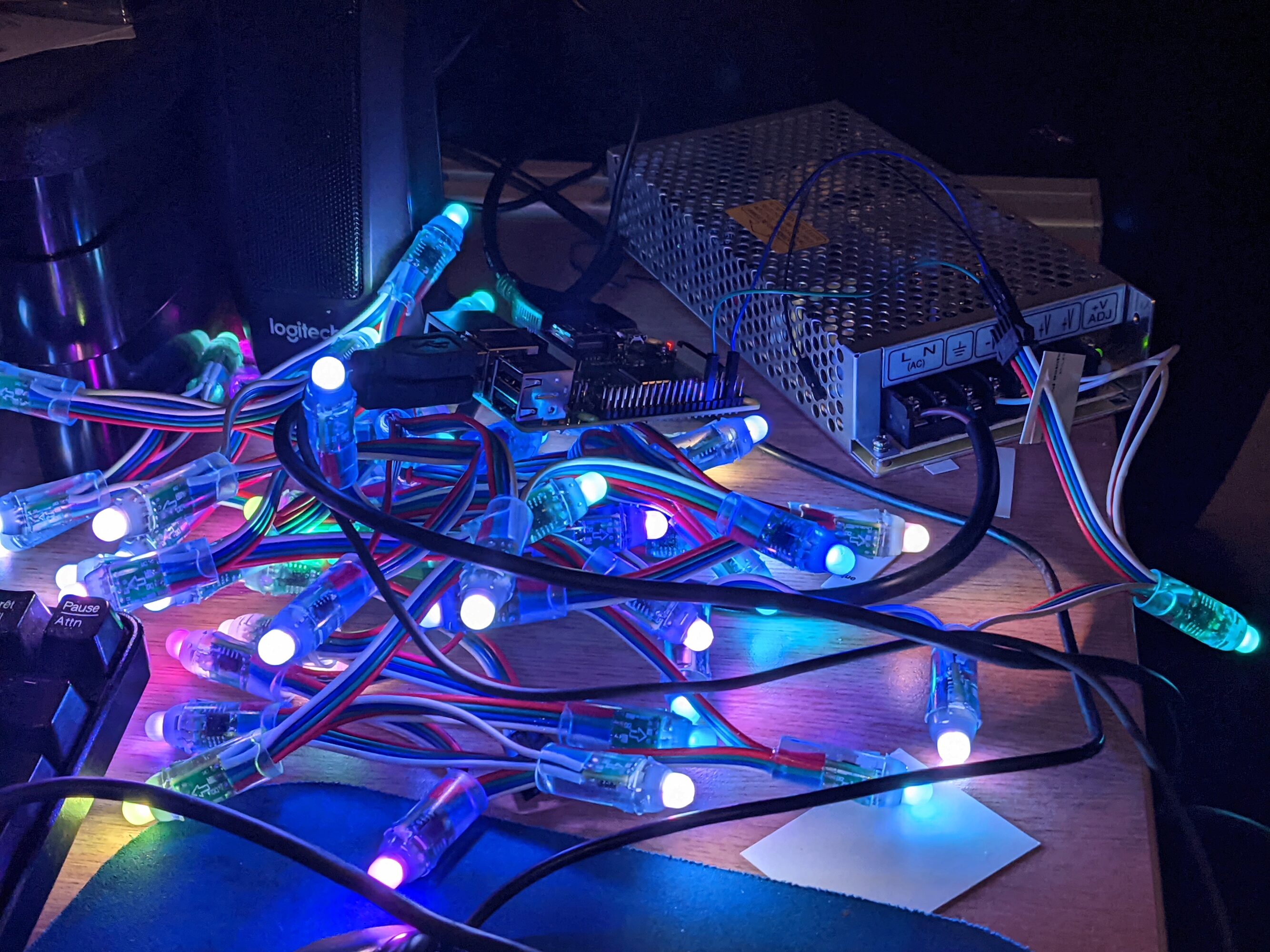

Hardware#
The hardware used was rather typical for a project like this:
- LED strips: five "WS281x" addressable LEDs, for a total of 250 LEDS. The strip we bought were advertised as "WS2811", but they have four cables rather than three, which suggest that they are WS2801 instead. The additional wire is apparently a backup data cable in case the LED burns. Information online is hard to come by due to the mixup by the provider (see "Wiring").
- webcam: standard run of the mill webcam
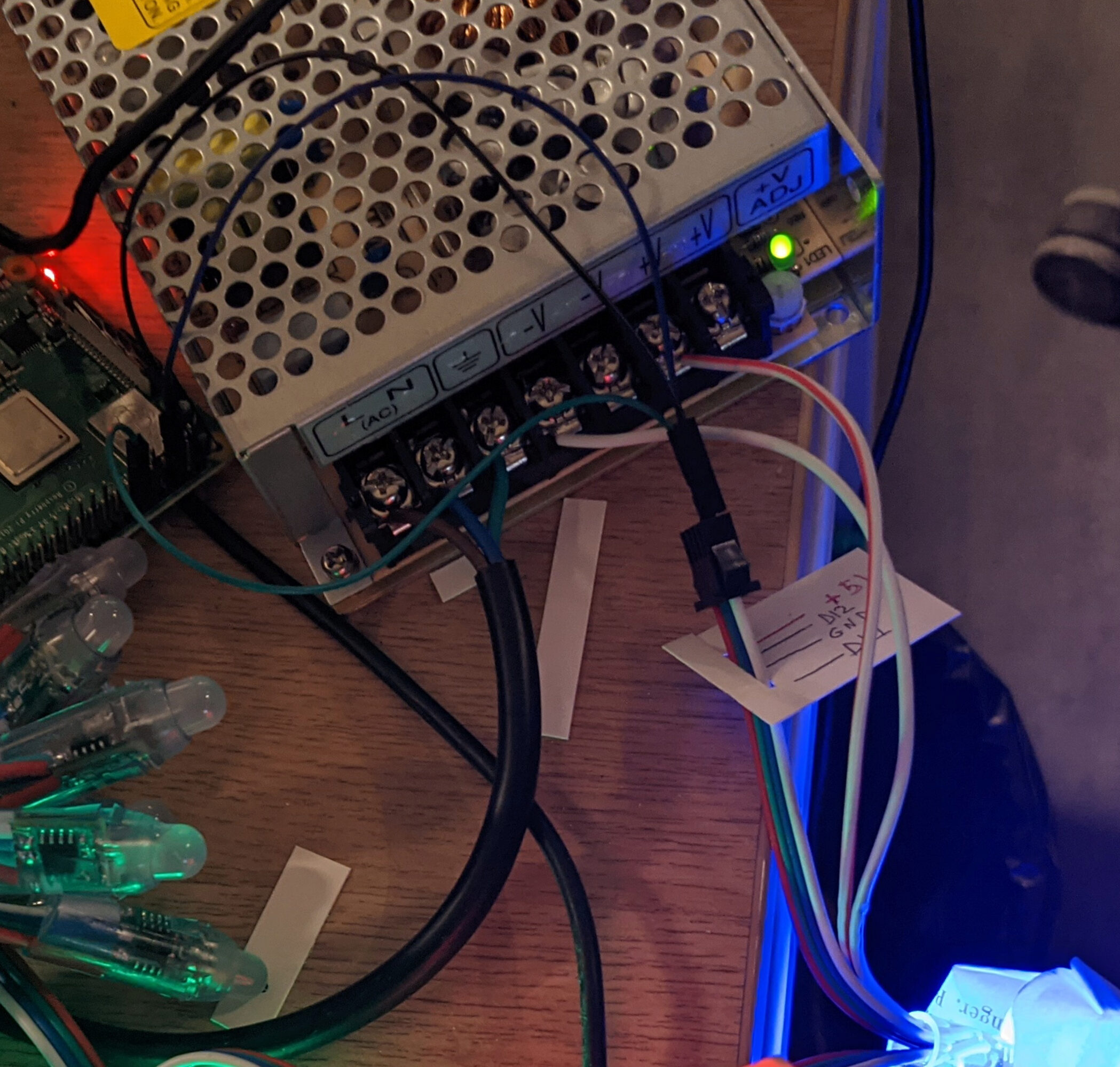
- power supply: typical 5V/25A LED Power Supply Unit, to accomodate for the 60mA * 250 = 15A at full power
- paper boxes: traditional "water bomb" origami, 250 of them
Wiring#
As mentionned above, wiring turned out to be a bit difficult as the LEDs weren't properly labeled. But it turned out fine.
On the first LED strip, the blue (ground, GND) cable was plugged to one of the ground pins of the Raspberry Pi (#6, see the schematics, and the white wire to the GPIO18. Then, each strip received power from a "bus" cable, which is itself plugged into the power supply.
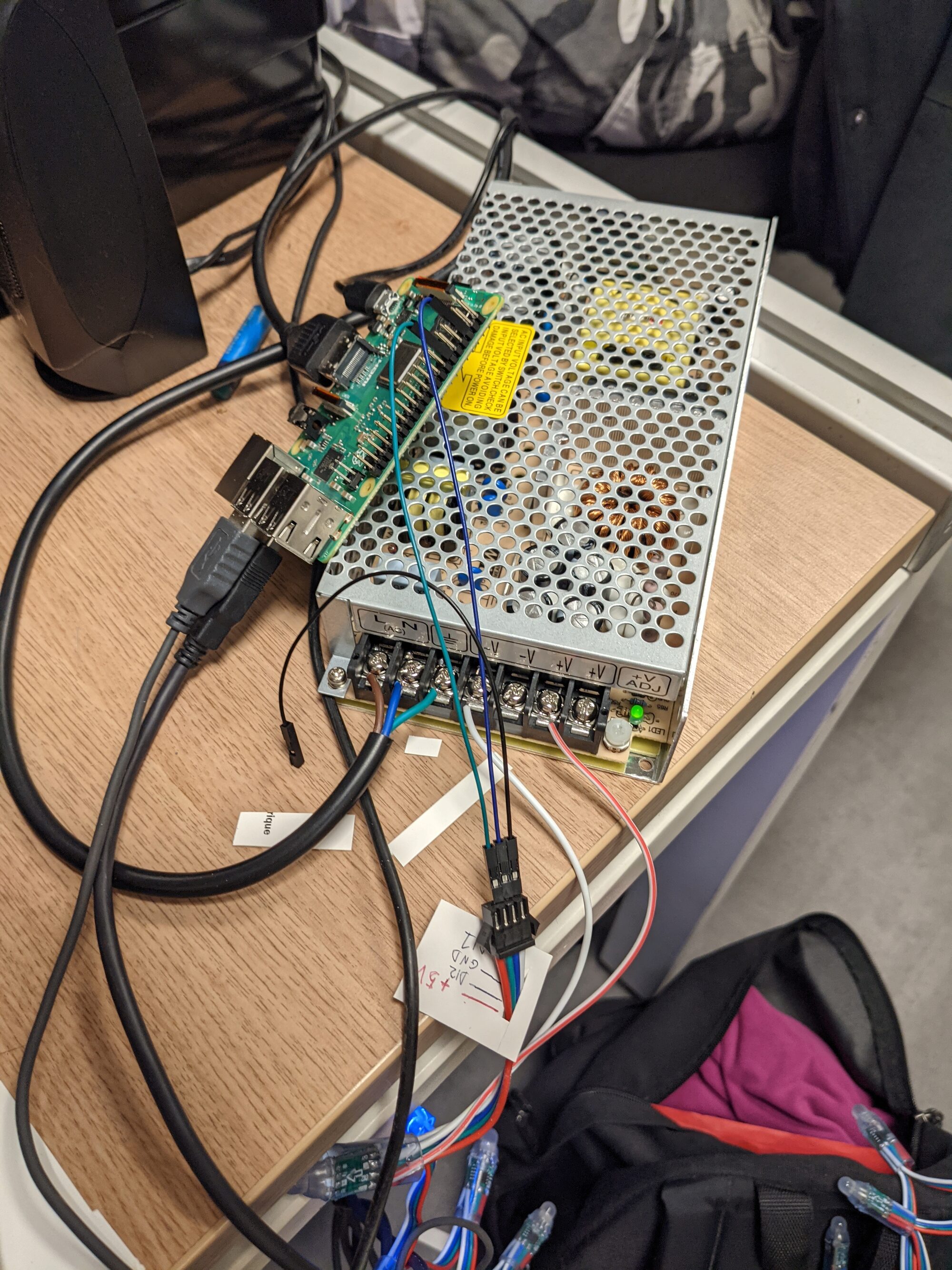
I'm used to work with both low power (such as electronic projects) and "high" power (such as house wiring), but here the mix of high intensity and low voltage weirded me out. But the small wires seemed to be enough, as it didn't not caught on fire nor released magic smoke even after several hours of continuous running.
Code#
The code was written in Python, using OpenCV (cv2) to get data from the webcam, process it (resizing and flipping) and show the intermediate result in a windows, and the rpi_ws281x library to drive the LED strips.
Thanks to the rpi_ws281x library, initialising the LED strip is pretty easy:
 1 # LED strip configuration:
 2 LED_COUNT      = 250 # Number of LED pixels.
 3 LED_PIN        = 18      # GPIO pin connected to the pixels (18 uses PWM!).
 4 #LED_PIN        = 10      # GPIO pin connected to the pixels (10 uses SPI /dev/spidev0.0).
 5 LED_FREQ_HZ    = 800000  # LED signal frequency in hertz (usually 800khz)
 6 LED_DMA        = 10      # DMA channel to use for generating signal (try 10)
 7 LED_BRIGHTNESS = 200 #255     # Set to 0 for darkest and 255 for brightest
 8 LED_INVERT     = False   # True to invert the signal (when using NPN transistor level shift)
 9 LED_CHANNEL    = 0       # set to '1' for GPIOs 13, 19, 41, 45 or 53
10
11 REFRESH_RATE_MS = 10
12
13 strip = Adafruit_NeoPixel(LED_COUNT, LED_PIN, LED_FREQ_HZ, LED_DMA, LED_INVERT, LED_BRIGHTNESS, LED_CHANNEL)
14 # Intialize the library (must be called once before other functions).
15 strip.begin()
Changing a LED colour is then done like this:
1 strip.setPixelColor(10, Color(255,0,0)
2 strip.show()
The RGB order didn't seemed to correspond between the webcam and the strip, so I hacked around a translator: as per commented, it might over complicated, but this is a hacky project and it worked:
 1 def cam_pixel_to_color(frame,x,y):
 2     """
 3     takes a cv2 frame, and return the pixel colour at (x,y) as Color
 4     while converting BGR (cam) to appropriate RGB
 5
 6     While working RGB order might be convoluted, to fix
 7
 8     """
 9
10     try:
11         colour = Color(
12                     int(frame[y][x][1]), #B -> G
13                     int(frame[y][x][2]), #G -> R
14                     int(frame[y][x][0]) #R -> B
15                )
16
17         return colour
18     except Exception as e:
19         print(f"[WARNING] Out of Bound on camera for ({x}, {y})")
20         return Color(0,0,0)
21
22     return -1
Finally, as the strip was hung in "loops" on a support, I made some index shenanigans to unroll the image in reverse every other row:
1 def led_xy(x,y,color):
2     if (x % 2):
3         i = x * 25 + (25 - (y + 1))
4     else:
5         i = x * 25 + y
6     strip.setPixelColor(i, color)